PLC programming is the set of techniques and languages used to define the behavior of a Programmable Logic Controller, the electronic device at the core of industrial automation.
Through software, a PLC is able to read signals from the factory floor, process them, and control machines and processes with precision and continuity.
In this article, we will explore what a PLC is, how it works, which programming languages are most widely used, how this technology has revolutionized industry, and which skills are required to work in this field of automation.
We will also discuss components, the scan cycle, the history of PLCs, practical applications, and much more.
Finally, you will find useful guidance on accessing specialized training programs, including those offered by our Academy, designed for those who want to enter the field or take a significant step forward in their career.
Contents
PLC Programming: What Is It?
PLC programming is the activity through which the logic that allows a Programmable Logic Controller to autonomously manage machinery and processes is defined.
Programming a PLC means translating the operational requirements of a system—such as starting a motor, controlling temperature, or coordinating a series of movements—into instructions that the controller executes cyclically with precision (when programmed correctly, of course).
During its normal scan cycle, the PLC reads incoming signals from sensors (inputs), processes them through the CPU, and activates the system via valves, actuators, or motors, in order to manage every phase of the production process within the required timing and operating conditions.
To describe these logics, standardized programming languages are used, as defined by the IEC 61131‑3 standard, which represents the international reference for PLC programming.
This standard establishes a shared set of languages to ensure uniformity, compatibility, and greater accessibility for operators with different backgrounds.
Among the most widely used languages, we can identify three main categories:
- Ladder Diagram is probably the most well-known and widely used language. Its strength lies in the fact that it visually mirrors traditional electrical schematics. Contacts, coils, and relays are represented graphically within a “ladder” structure. This similarity makes it particularly intuitive, as it translates already familiar concepts into digital logic that can be implemented in a PLC.
- Function Block Diagram offers a block-based representation, with blocks connected to one another through input and output signals. Thanks to this graphical structure, it makes it easy to visualize data flow between the different logical components of an automation system, making it especially suitable for systems that require deeper interconnection.
- Structured Text, finally, is a high-level textual language similar to languages such as Pascal or C. It allows more complex operations (such as loops, nested conditions, and mathematical functions) to be managed using a flexible syntax. It is often used when the logic to be implemented goes beyond simple contact or block management, entering the realm of algorithms or more advanced operations required by the system.
The combined use of these languages, made possible by the IEC 61131‑3 standard, gives programmers the freedom to choose the most suitable approach for each part of the system, with the goal of optimizing development and maintenance.
Standardizing languages therefore ensures that system logic remains understandable and modifiable over time, regardless of who developed it or the PLC manufacturer.
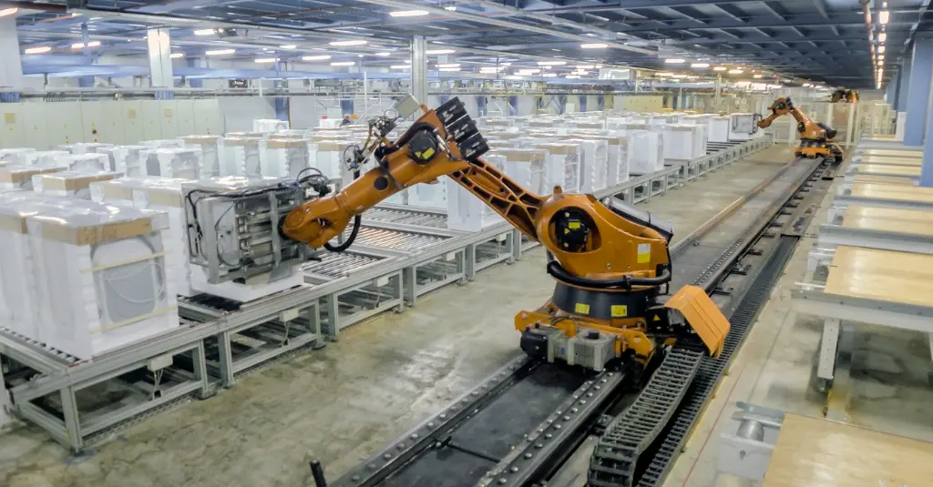
Thanks to the ability of PLC programming to transform complex operational requirements into structured and repeatable logic, it becomes the true heart of industrial automation.
Without well‑designed software, a PLC would not be able to interpret sensor signals or coordinate the actions of actuators, thereby compromising the entire production process.
Programming defines what the system must do, how it must do it, and when.
It is therefore the component that makes a factory intelligent and brings order to a set of devices that, taken individually, would not be able to behave coherently.
It is no coincidence that the PLC is often described as the “brain” of a plant. From alarm management to variable control, from interlocking to start‑up sequences: this logic makes it possible to maintain a continuous, safe, and efficient production cycle—essential factors for any process that aims to be competitive.
The central role of PLC programming also emerges when compared with the control systems that preceded it.
Before the introduction of PLCs, automation functions were managed through complex wiring of relays and timers. These systems were rigid, difficult to modify, and costly to maintain.
The arrival of PLCs made it possible to replace “hard‑wired” logic with software‑based solutions that are far more scalable and manageable, since they can be modified with just a few lines of code without physically intervening on the system.
This, as mentioned, reduced maintenance time and costs—but that’s not all.
PLCs enabled rapid reconfiguration of production lines and encouraged the adoption of agile manufacturing models.
Moreover, they play a key role in the evolution of modern factories, as today they are no longer limited to controlling actuators and sensors, but also integrate functions such as network communication, predictive diagnostics, motion control, and data exchange with supervisory systems and digital platforms.
Thanks to these capabilities, the PLC has become one of the pillars of Industry 4.0.
One could say that without PLCs, modern automation simply would not exist.
Who Invented the First PLC, and Why?
In the late 1960s, the manufacturing industry—particularly the U.S. automotive sector—was facing a major problem.
Assembly lines were controlled by complex relay-based systems and huge panels filled with electromechanical components, which were prone to frequent failures. Any change in production required complete rewiring and, as a result, weeks of downtime and exorbitant maintenance costs.
This was a particularly pressing issue for General Motors, which, like many major car manufacturers, needed greater flexibility to update production lines and introduce new models on a yearly basis.
Production was clearly inefficient and increasingly incompatible with the growing push toward automation based on emerging digital technologies.
It was General Motors’ Hydramatic division that first formally defined the need for a new control system capable of meeting the parent company’s specifications, which explicitly required a device that was:
- free of mechanical components subject to frequent replacement;
- reprogrammable, so that process changes could be made solely through software;
- resistant to vibration, dust, temperature fluctuations, and electrical interference;
- maintainable without the need for computer specialists;
- capable of diagnosing faults and thereby reducing long machine downtime.
These requirements could not be met by existing systems.
This is where Richard “Dick” Morley enters the scene.
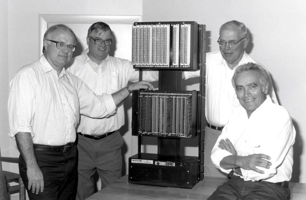
After an initial period working as a machinist at MIT and various experiences ranging from radar technology to electronics, Morley founded Bedford Associates in 1960.
Convinced that industrial systems should be designed around the needs of operators, he believed that engineering should first and foremost simplify their work. His idea was to create a single reusable device capable of adapting to different contexts without having to start from scratch each time.
In 1968, he therefore wrote the specifications for a new type of controller: no longer hard‑wired logic, but a programmable industrial computer that was robust, modular, and easy to update—exactly what General Motors, and indeed the entire manufacturing industry in the country, was looking for.
Morley described his approach as an “exercise in application.” What mattered was not the technology itself, but the controller’s ability to solve real problems simply and quickly. This was the philosophy behind the first PLC and the reason for its long‑term global success.
The Modicon 084 project is considered the first Programmable Logic Controller in history.
With an almost legendary name, according to a well‑known account, the Modicon 084 was Bedford Associates’ 84th attempt to obtain a working prototype—testimony to the persistent determination of Morley and his collaborators. Shortly thereafter, the 084 prototype evolved into the Modicon 184, ready for mass production.
General Motors invested a considerable sum in purchasing an initial batch, finding in the Modicon the solution it had long been seeking and thus initiating the widespread adoption of the PLC.
It was an incredible achievement, made possible above all by one of Morley’s insights—perhaps his most brilliant one: the introduction of ladder logic as a programming language.
Unlike textual computer languages, which were far removed from operators’ experience, ladder logic was designed to visually mimic the relay circuit diagrams already in use.
As a result, the transition from traditional systems to PLCs did not require a change in skill sets, because operators could read the program just like a standard electrical schematic.
This choice had three fundamental effects:
- It drastically reduced the learning curve. Operators did not need to reinvent themselves as programmers. What they had previously drawn on paper or wired physically was simply represented digitally on a screen.
- It removed cultural barriers to technology. In factories of the 1960s and 1970s, distrust of computer programming was widespread. Using a visual language made it possible to bypass resistance and facilitate the digital transition.
- It enabled rapid, large‑scale adoption. Since factory personnel were already familiar with the logic of contacts and coils, the required training was minimal. Companies could therefore integrate PLCs without interrupting or completely rethinking their production processes.
Ladder logic became a true cultural bridge between the world of electromechanical automation and the new era of industrial automation, giving PLCs a decisive advantage over other experimental solutions of the time, which were based on approaches entirely foreign to factory technicians.
Morley’s invention marked the beginning of the third industrial revolution, accelerating the widespread adoption of microprocessors and laying the foundations for the technological evolution of the following decades—leading up to the interconnected systems that characterize Industry 4.0 architectures.
How a PLC Works
We know that a PLC is a digital electronic controller designed to reliably and continuously manage industrial processes and machines.
Its main characteristic is its ability to collect signals from the field, process them according to a user program, and control actuators or other devices, enabling the automation of even very complex sequences.
We now come to a second central point of our discussion: understanding how a PLC works.
Basically, a PLC is able to perform its tasks thanks to the interaction of specific components:
- the CPU, which processes data and manages the scan cycle;
- the memory, where the program, process data, and system functions are stored;
- the input and output modules, which connect signals from the physical factory to the digital domain;
- the power supply system and programming unit, which are essential respectively for safe operation and for developing the user software.
To better understand the relationship between these parts, we present below a table that summarizes their characteristics and the role they play in the operation of a PLC.

After taking a close look at the subcomponents that make signal management and transformation possible within a PLC, let us briefly see how all these parts operate together over time.
The actual operation of a PLC takes shape in what is known as the scan cycle, that is, a sequence of operations that the CPU executes continuously.
In each cycle, the CPU acquires the state of the system by reading the copy of the signals coming from the sensors, which is stored in the input process image. Once these data have been collected, the CPU executes the user program, stepping through the stored instructions and applying logical operations, comparisons, timing functions, and calculations through the ALU and internal registers.
After processing is complete, the CPU updates the outputs, transferring to the I/O modules the decisions that must be applied to actuators, motors, or control devices in the system.
This cycle of reading, processing, and updating can occur hundreds of times per second and ensures that the controller constantly responds to changes in the process. At the same time, internal systems such as self-diagnostics and the watchdog circuit monitor correct operation, stopping the PLC under unsafe or abnormal conditions.
At the core of the scan cycle is the user program.
The instructions that make up the program are created using textual or graphical languages (including the widely used Ladder Diagram) and define exactly how the PLC must react to incoming signals, which conditions to evaluate, and which actions to take.
During each scan, the CPU translates the user-written code into commands that regulate the plant.
In the balance between signal acquisition, instruction execution, and output updating, the complete operation of the PLC becomes evident.